PCB Design · Mixed Signal · Built
Arduino Uno I/O Shield
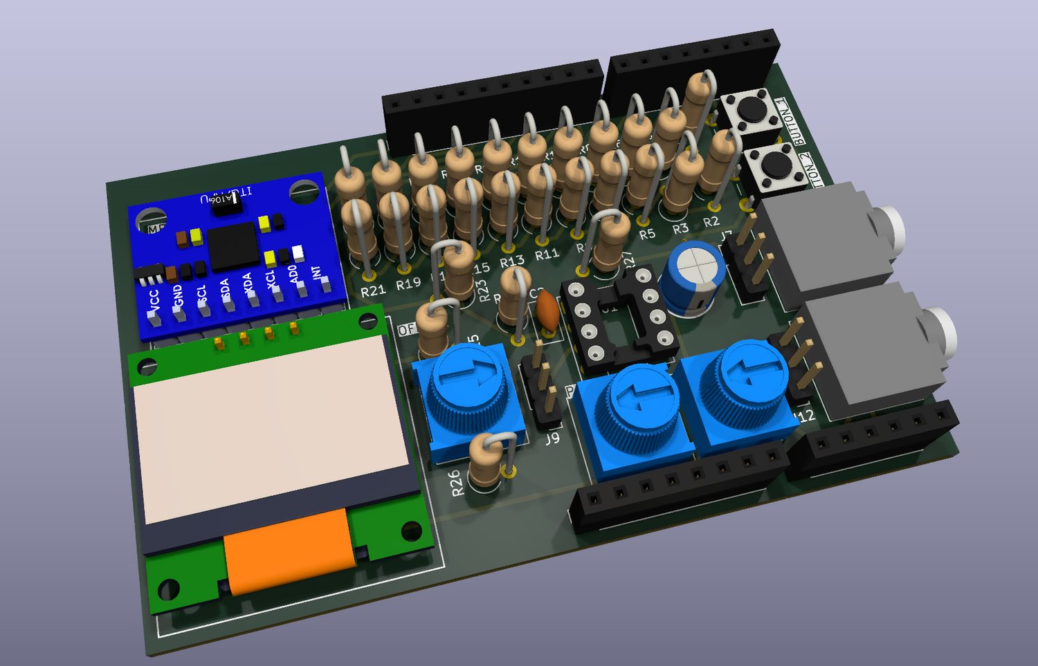
- Form factor
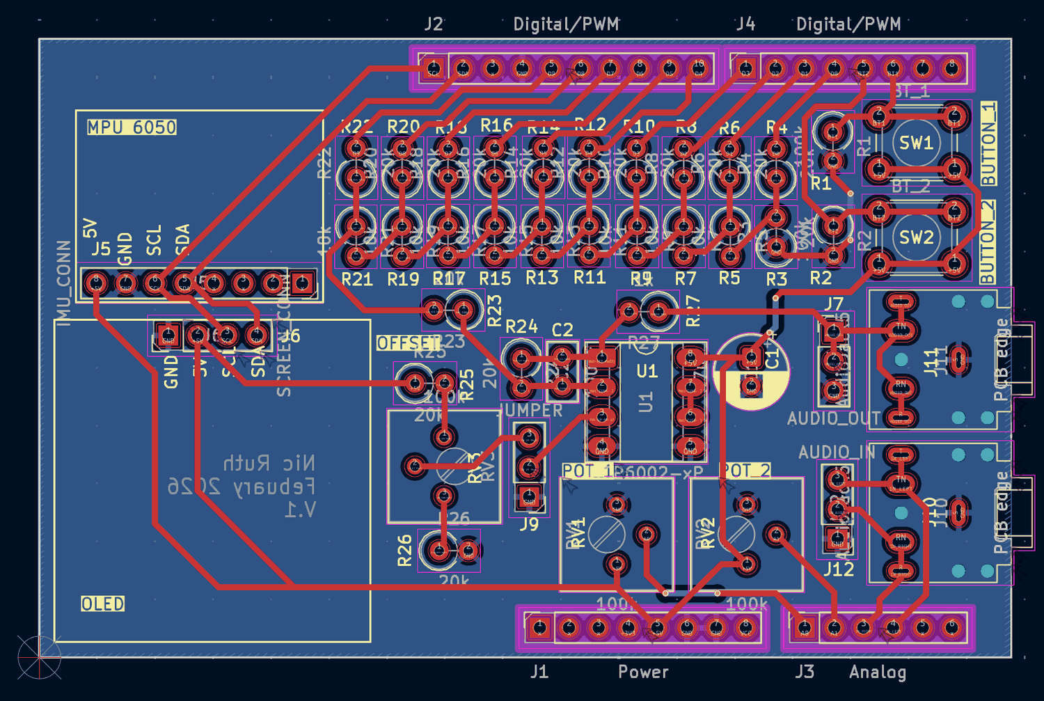
- Arduino Uno shield
- DAC
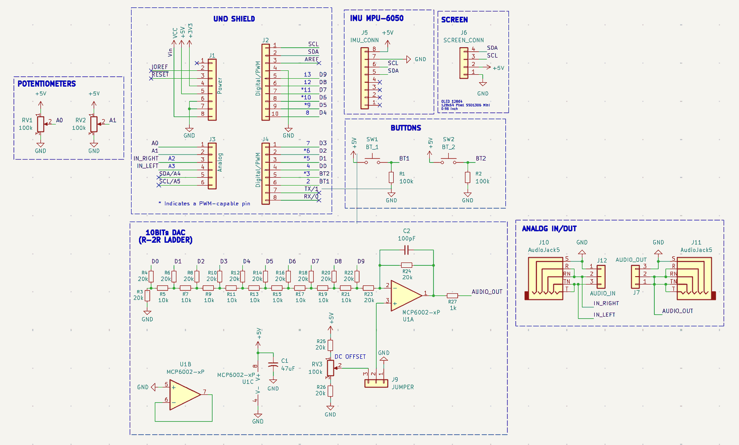
- 10-bit R-2R ladder, 10 kΩ / 20 kΩ, on D0–D9
- Output buffer
- MCP6002 rail-to-rail op-amp, 100 pF feedback cap
- Analog I/O
- Two 3.5 mm jacks: line in to A2 / A3, buffered line out
- Sensing
- MPU6050 IMU header (I²C)
- Display
- SSD1306 128 × 64 OLED header (I²C)
- Controls
- Two 100 kΩ pots to A0 / A1, two buttons, DC-offset trimmer
- Tool
- KiCad
- Status
- Fabricated and hand-soldered
Why a DAC
An Arduino Uno can't output a real analog voltage. Its
analogWrite is PWM, a square wave switching between
0 V and 5 V. If you need an actual varying voltage, like for audio,
you need a digital-to-analog converter, and the Uno doesn't have
one.
This shield makes one out of resistors. Ten digital pins, D0 through D9, feed an R-2R ladder made only of 10 kΩ and 20 kΩ resistors. Each step counts half as much as the one above it, so writing a 10-bit number to those pins gives a proportional voltage. That's 1024 levels from two resistor values, with no DAC chip.
Why the ladder needs a buffer
An R-2R ladder has a real output impedance, so anything you connect to it becomes part of the divider. If you plug in something with a low input impedance, like a speaker, the output voltage sags and isn't accurate anymore.
So the ladder feeds an MCP6002, a rail-to-rail op-amp wired as a buffer. It has a very high input impedance, so it doesn't load the ladder, and a low output impedance to drive whatever comes next. A 100 pF cap across the feedback path rolls off the high end and smooths the steps.
A trimmer sets a DC offset through a jumper, so the output can be centered where the next stage needs it.
Jacks instead of jumper wires
Both ends of the analog path use 3.5 mm jacks. Line in goes to analog pins A2 and A3, and the buffered line out has its own jack. That means the board connects to normal audio gear with a regular cable, instead of jumper wires and alligator clips every time.
The rest of the board is there so I don't have to rebuild a breadboard each time: two 100 kΩ pots on A0 and A1, two buttons with pull-downs, and headers for an MPU6050 IMU and a 128 × 64 SSD1306 OLED, both on the same I²C bus.
Related work
This is one of two Uno shields I've designed. The other is the DemoSat balloon payload, which uses the same shield outline for a set of sensors.