RF · Analog
FM Radio Receiver
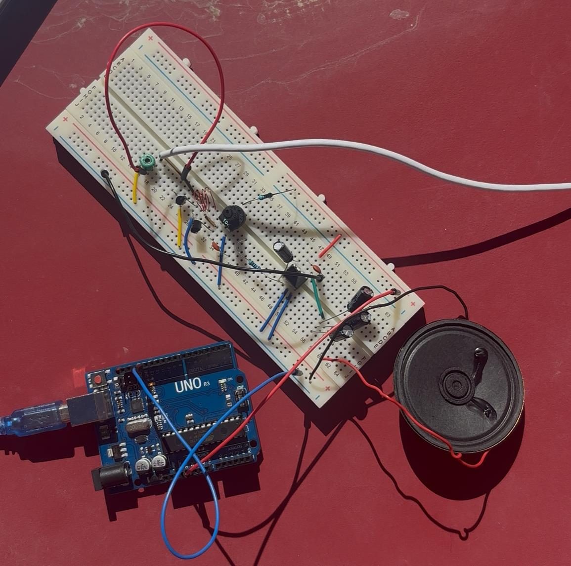
- Band
- 88–108 MHz (FM broadcast)
- Tank inductor
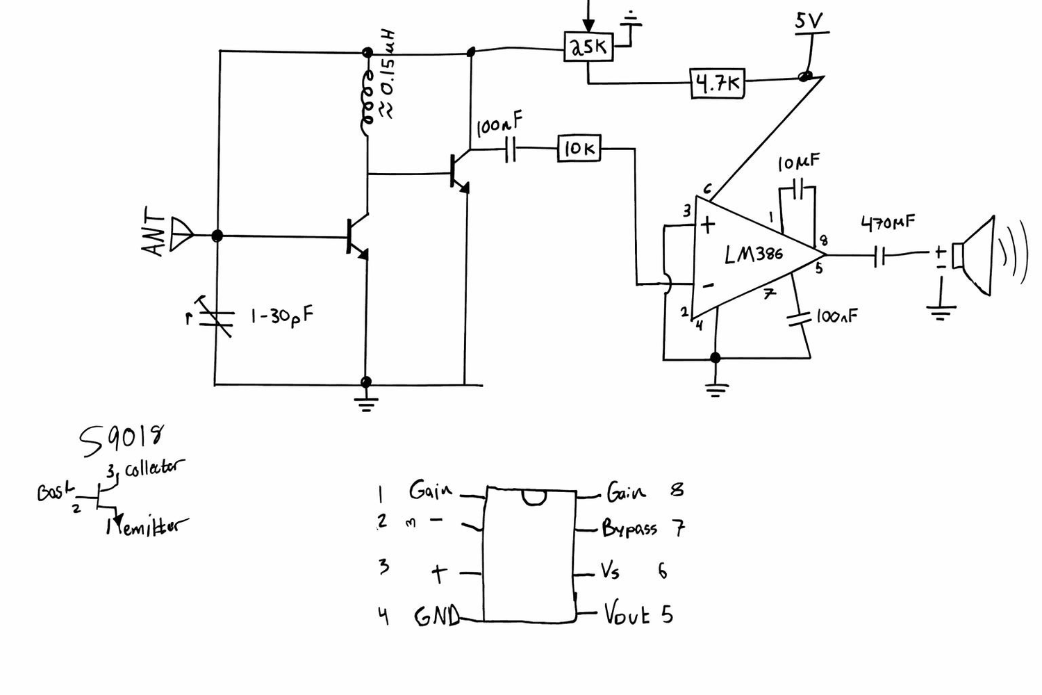
- ≈ 0.15 µH, 28 AWG enamel, 3–4 turns, 5.3 mm dia, 3 mm long
- Tuning
- 1–30 pF variable capacitor
- RF stage
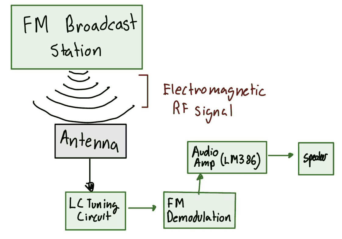
- Two transistors (S9018 specified, substitutes used)
- Audio stage
- LM386 into a speaker via 470 µF
- Supply
- 5 V from an Arduino Uno
- Built for
- Principles of Communications coursework
What it is
An FM broadcast receiver built from individual parts, with no receiver IC, for a Principles of Communications class. It's an antenna, an LC tank, two transistor stages, an LM386 and a speaker.
It did receive. Once it was put together it picked up one strong local station and held it. Almost nothing else worked the way the design said it should, and working out why is most of what I got out of it.
Winding the coil
The front end is an LC tank, and at 100 MHz the inductor only needs to be a few tenths of a microhenry. You can't really buy that off the shelf, so I wound it by hand: 28 AWG enameled copper, three to four turns around a drill bit, about 5.3 mm across and 3 mm long, with the ends sanded to get through the enamel. That works out to roughly 0.15 µH.
With a 1–30 pF variable capacitor, that should cover the whole 88–108 MHz band, so turning the tuning knob should change stations.
What actually happened
Three things went wrong:
- The variable capacitor did nothing. Sweeping it end to end produced no change in what was received.
- Changing the number of turns on the coil was negligible. Rewinding it, which is the other half of setting the resonant frequency, barely changed the result either.
- There was significant noise, and antenna position mattered far more than any control on the board.
Together, those mean the tank wasn't what set the tuning. If changing both L and C doesn't move the resonant frequency, then stray capacitance and lead inductance somewhere else in the circuit must be bigger than the parts that were supposed to set it. That's very possible on a solderless breadboard. The contact strips have a few picofarads between neighbors, which is a big chunk of a 1–30 pF tuning range, and the jumper wires add about as much inductance as the coil.
The transistors are the other suspect. The design called for the S9018 because of its gain-bandwidth at VHF, but I had to use substitutes. If a transistor runs out of gain before 100 MHz, the receiver stops acting tuned and just responds to whichever signal is strongest.
What a version two would change
Solder it. Almost every problem above comes from building a VHF circuit on a breadboard. A soldered board with short leads and a ground plane would get rid of most of the parasitics. Using the actual S9018s instead of substitutes would give the RF stage the bandwidth the design assumed. After that, a dedicated demodulator IC would give much cleaner audio than two discrete stages.
I don't count it as a failure. It picked up a station on a breadboard full of loose parts, and I can explain why it didn't do more.