Analog Design · Unfinished
Battery Tester Board
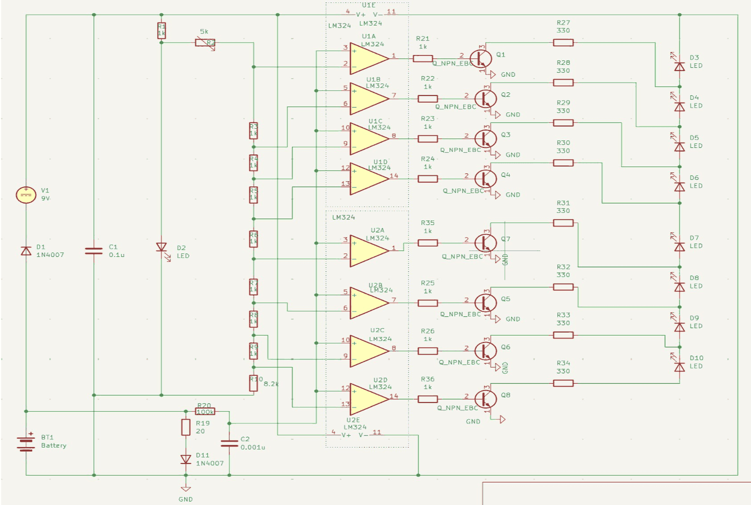
This one stopped at the schematic. The schematic is done, but the term ended before layout, so there's no board and nothing has been measured. I'm including it for the circuit design, not because it's been shown to work.
- Readout
- Eight LEDs as a bar graph
- Comparators
- Two LM324 quad op-amps, eight channels
- Reference
- 1 kΩ ladder with an 8.2 kΩ tail, 5 kΩ trimmer for calibration
- Test load
- 20 Ω through a 1N4007, across the cell under test
- Drive
- NPN per channel, 1 kΩ base, 330 Ω LED ballast
- Supply
- 9 V, reverse-protected, with a power-on indicator
- Tool
- KiCad
Why it tests under load
A multimeter across a worn-out AA will often read close to 1.5 V, but the same battery dies right away in a device. The open-circuit voltage says very little about whether a battery can still supply current. What matters is what the voltage does under load.
So the circuit puts a 20 Ω resistor across the battery, through a 1N4007, as a load. Everything after that measures the battery while it's supplying current, and a battery with high internal resistance sags in a way it wouldn't with nothing connected.
The comparators
The readout is a bar graph of eight LEDs, each lighting once the battery passes a slightly higher threshold. That takes eight comparators, and two LM324 quad op-amps give exactly eight.
Each comparator's reference comes from a single chain of 1 kΩ resistors with an 8.2 kΩ tail, tapped at eight points. Since every threshold comes from the same chain, they can't drift relative to each other. A 5 kΩ trimmer at the top of the chain shifts all eight together, so the scale can be calibrated for a particular battery type.
An LM324 output can't drive an LED very brightly, so each channel drives an NPN transistor through a 1 kΩ base resistor, with 330 Ω setting the LED current. The 9 V supply has a series 1N4007 to protect against connecting it backwards, and its own power LED.
Where it stopped
The schematic is finished, but the board isn't. The term ended before layout, fabrication or any measurements, so the threshold spacing hasn't been checked against real batteries and I haven't confirmed 20 Ω is the right load.
I left it on the site because the design is still worth showing, as long as it's clear it was never built.